
NTC Temperature Daughterboard
The NTC temperature daughterboard is a stackable module for the RP2350 motherboard. It provides eight channels of precision temperature measurement using NTC thermistors in Wheatstone bridge configurations, connected via standard Cat5 cabling.
Solar thermal systems need reliable temperature readings from sensors mounted in hostile environments — on rooftops, inside hot water tanks, on collector panels, and alongside inverters and pump motors. The sensors must work continuously for years without maintenance, survive temperature extremes, tolerate electrical noise, and cope with long cable runs. Getting this wrong means false readings, wasted energy, or equipment damage.
Why NTC thermistors?
There are three common approaches to electronic temperature measurement: one-wire digital sensors, platinum RTDs, and NTC thermistors. We evaluated all three and chose NTC for good reasons.
Problems with one-wire digital sensors
One-wire sensors like the DS18B20 are popular in hobbyist projects. They are cheap, easy to wire, and give a direct digital temperature reading with no analog circuitry. But they have serious limitations for solar thermal use.
Maximum temperature
The DS18B20 is rated to 125 C. Solar collector stagnation temperatures can exceed 200 C, and even normal operating temperatures regularly reach 90-100 C in summer. Running a semiconductor device near its maximum rating for sustained periods accelerates ageing and drift. NTC thermistors are passive devices — glass-encapsulated types are rated to 300 C and do not degrade with sustained heat exposure.
Glitches and data integrity
One-wire sensors communicate digitally over the same wire that powers them. The protocol is timing-sensitive, and the sensor contains an on-board ADC, digital logic, and a ROM. Any of these can glitch. In practice, DS18B20 sensors are known to occasionally return readings of exactly 85 C (the power-on default) or -127 C (a communication error) in the middle of normal operation. In a solar thermal controller, a spurious 85 C reading from a tank sensor could shut down a pump that should be running, or a -127 C reading could trigger frost protection heating in summer.
These glitches can be filtered in software, but the fundamental problem remains: you are trusting a piece of active silicon mounted in a hostile environment to correctly digitise, store, and transmit a temperature reading every time. The failure mode is silent and intermittent. If you look at our historic data you will sometimes see these glitches as we used one-wire sensors for air and tank temperatures.
Absolute reliability
An NTC thermistor is a resistor. It has two wires and no active electronics. It cannot glitch, cannot return a power-on default, and cannot have a firmware bug. Its resistance is a direct physical consequence of its temperature. If the thermistor is intact and connected, the reading is correct. If the cable is broken, the resistance goes to infinity — an unambiguous fault that is trivial to detect. There is no intermediate state where the sensor appears to be working but is returning wrong data.
For a system that runs unattended for years and controls pumps, valves, and heating elements, this kind of deterministic behaviour is more valuable than convenience.
Parasitic power problems
One-wire sensors in parasitic power mode draw operating current through the data line. On long cable runs, the voltage drop can cause the sensor to brown out during temperature conversion, which is when it draws the most current. This leads to intermittent failures that are difficult to diagnose because they depend on cable length, temperature, and timing. Dedicated power wiring solves this but eliminates the one-wire advantage.
Problems with platinum RTDs
Platinum resistance thermometers (PT100, PT1000) are the gold standard for laboratory and industrial temperature measurement. They are accurate, stable, and linear. But they bring their own problems in field-deployed solar systems.
Cost
A PT100 sensor element costs several times more than an NTC thermistor. The bigger expense is the signal conditioning: platinum RTDs have small resistance changes per degree (0.385 ohms per degree for a PT100), so they need precision low-noise amplifiers, often instrumentation amplifiers, and precision reference resistors. An NTC at 25 C changes by roughly 400 ohms per degree — over a thousand times the sensitivity of a PT100. This large signal can be read directly by a standard ADC without amplification.
Amplifier fragility
The small signal from a PT100 (0.385 ohms per degree) must be amplified before it can be digitised. This amplifier has to be located close to the sensor to avoid picking up noise on the long cable run between the sensor and the controller. That means placing a precision analog circuit — an instrumentation amplifier, reference resistors, decoupling capacitors — at the sensor end, exposed to the same hostile environment as the sensor itself: temperature extremes, humidity, condensation, and voltage transients from nearby pump motors and inverters.
These are exactly the conditions that degrade precision analog components. Every active part in the signal chain is something that can drift, fail, or be damaged by a transient. An NTC into a Wheatstone bridge needs no amplification at all: the bridge output is millivolts, well within the range of a 16-bit differential ADC mounted safely on the controller board.
We have had repeated failures from platinum sensors mounted at the top of our test rig.
Diminishing returns
PT100 accuracy matters when you need 0.01 C resolution for calibration laboratories or pharmaceutical processes. Our solar thermal controller uses proportional pump speed control based on the temperature difference between the collector panel and the tank — the pump ramps linearly from minimum to maximum speed over a 10 C range, calculated in 0.1 C steps. This means sub-degree accuracy does matter, but the 0.1-0.2 C accuracy of a well-characterised NTC with Steinhart-Hart coefficients is more than sufficient. The additional precision of a PT100 would not produce a meaningfully different pump speed. Paying for platinum accuracy adds cost and complexity without improving control behaviour.
Board design
The daughterboard carries the ADS1115 16-bit ADC, CD74HCT4066 analog switches for channel multiplexing, and RJ45 connectors for eight sensor channels. Each remote sensor is a small PCB with the NTC thermistor mounted in a full Wheatstone bridge. The bridge, its resistors, and the thermistor are all at the measurement point — the cable only carries power and sense signals back to the daughterboard.
Why the bridge is at the sensor end
If the bridge were at the controller, the cable resistance would be in series with the NTC, corrupting the measurement. By placing the bridge at the sensor, the measurement happens where the temperature is. The cable becomes a simple transport for voltages that are already proportional to temperature.
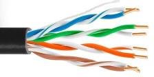
Cat5 cabling
Each sensor connects via a standard Cat5 cable using all four twisted pairs:
| Pair | Function |
|---|---|
| 1 | Bridge excitation (V+ and GND) |
| 2 | Differential sense (nodes A and B) |
| 3 | Cable resistance measurement |
| 4 | Indicator LED |
Cat5 cable is cheap, readily available in any length, and uses standard RJ45 connectors that anyone can crimp. The twisted-pair construction provides natural common-mode noise rejection. Using an industry-standard cable also means field installation and replacement require no specialist parts or tools.
Cancelling cable resistance
Even with the bridge at the sensor end, cable resistance still affects the excitation voltage arriving at the bridge. A 20-metre run of 24 AWG Cat5 has roughly 1.7 ohms per conductor. The excitation pair carries current, so the cable drops some voltage before it reaches the bridge.
We deal with this in two ways.
Remote force measurement
Rather than assuming the excitation voltage equals the supply, we measure it directly at the sensor end. The ADS1115 ADC has a dedicated differential channel wired to the bridge's supply rails at the sensor PCB. This "remote force" measurement reads the actual voltage arriving at the bridge after the cable drop.
For example, if the supply is 3.3V but the cable drops 0.15V, a naive calculation would use 3.3V and produce the wrong resistance. Instead, the remote force channel reads 3.15V — the true excitation at the bridge — and the resistance calculation uses that directly:
R_ntc = R4 x (V_remote_force / V_B - 1)
The sense pair carries no significant current (the ADC input impedance is very high), so cable resistance on the sense wires causes no voltage drop.
Direct cable resistance measurement
The third twisted pair is dedicated to measuring the cable resistance itself. This pair is shorted at the sensor end, so the measured resistance is purely the round-trip resistance of the wire. Since all four pairs in the same Cat5 cable have the same length and gauge, this measurement tells us the cable resistance for every pair.
The firmware can directly subtract the cable's contribution from any measurement where it matters. It also provides a diagnostic: if the measured cable resistance changes unexpectedly, it may indicate a damaged cable, a corroded connector, or a poor crimp — all common failure modes in field installations.
Common-mode noise rejection
Sensor cables in solar thermal systems run alongside mains wiring, inverter cables, and pump motor feeds. These sources radiate electromagnetic interference that couples into nearby conductors.
With twisted-pair cable, this noise couples equally into both wires of each pair — it appears as a common-mode voltage that shifts both conductors up and down together. A differential ADC measures the voltage between its two inputs, so common-mode noise cancels:
V_diff = (V_A + V_noise) - (V_B + V_noise) = V_A - V_B
The ADS1115 specifies a common-mode rejection ratio of over 100 dB at 50/60 Hz, meaning mains-frequency interference is attenuated by a factor of more than 100,000. The twisted-pair geometry of the Cat5 cable ensures the noise stays common-mode by exposing both conductors equally to any external field.
A single-ended ADC measurement would pick up this noise directly. In an environment with inverters switching at tens of kilohertz, this would make accurate millivolt-level bridge readings impossible without heavy filtering and shielding.
ADC and signal conditioning
We use the ADS1115, a 16-bit delta-sigma ADC from Texas Instruments, communicating over I2C. It operates in single-shot mode at 128 samples per second with a full-scale range of +/-4.096V.
Eight NTC channels are multiplexed through CD74HCT4066 analog switches into the shared ADC. Each channel has its own bridge resistor set, allowing different thermistor types to be mixed on the same board.
Filtering
Raw ADC readings are noisy, so each temperature measurement passes through a two-stage filter:
- Median filter — 8 raw ADC readings are taken and the median is selected. This rejects outlier spikes from electrical noise without smoothing the signal.
- Average filter — 8 median-filtered values are averaged. This reduces random noise while preserving the true signal.
The result is 64 ADC samples per temperature reading (8 x 8), giving stable readings even in electrically noisy environments. A 200ms settling delay after switching channels ensures the analog switches and bridge have stabilised.
Indicator LED
The fourth twisted pair drives an LED on the sensor PCB. This provides a simple visual confirmation during installation and troubleshooting that the sensor has power and the cable is connected. When diagnosing problems on a roof or in a plant room, being able to see at a glance which sensors are alive saves significant time.