The system we developed is modular, with modules connected on a 2-wire data bus, with an additional 2 wires for power. Up until now, we have generally used premade pcbs connected to our own boards for this. But this needed to change into a more professional solution. We wanted a bit more memory than the few kilobytes per module that we had as that would allow us more comfortable resource use – like different languages etc..
We want complete software configuration through a text-based menu, with the user simply plugging their phone or computer into the module and using a terminal emulator (as at present). The idea is that the user will always be able to configure the devices, irrespective of what operating system they have or what version, as there is no client software needed for this whatsoever. What works now will work in 10, 20, 30 years.
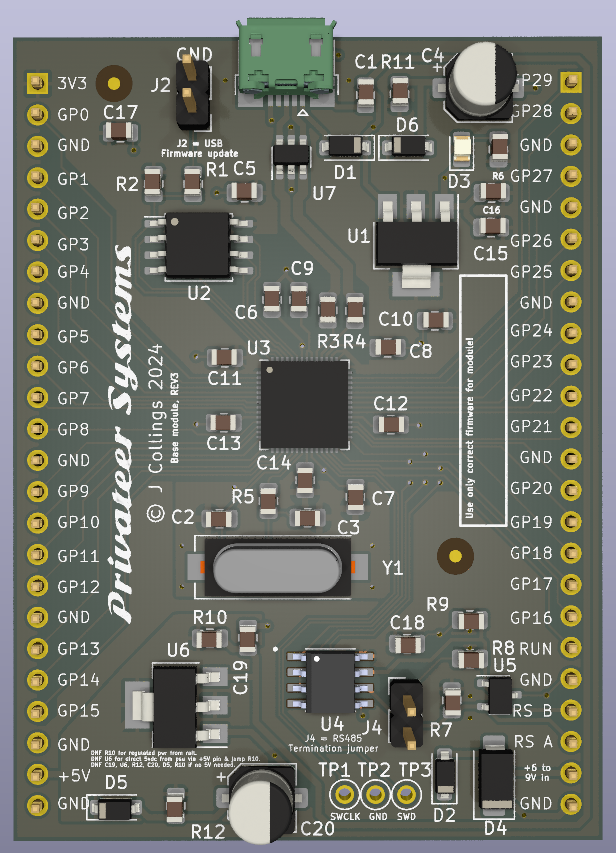
We also required RS485 comms built in and both 3.3 and 5-volt power, with good power conditioning and ESD protection etc. The firmware should be easily upgradable in the field. It needs to be robust and inexpensive.
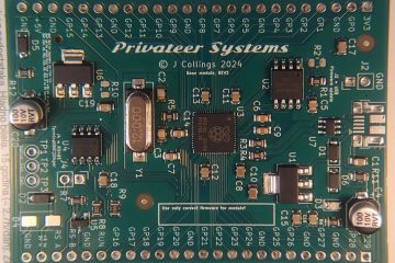
Accordingly, we developed the following new module:
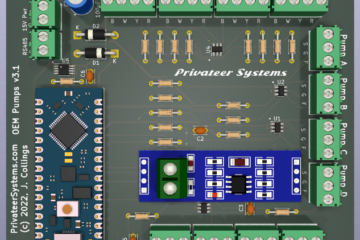
Now, each child module becomes trivial to develop – all it has to have is the specific circuitry for its role. For example, temperature sensors can be simple NTC sensors with a resistor divider and some ESD protection. Pump control becomes similar.
This new board has been fabricated and we’re testing it. Once that’s ok, we will redesign each part of the solar system to use it through a dedicated daughterboard, and tweak the code as needed.
Then we will continue testing and improving the whole system.