Differential Controller Ver 3.x
Overview
Our three channel differential controller prioritises heating of domestic hot water from the lowest cost source, and conserves heat in the domestic hot water tank when the heat source temperature drops.
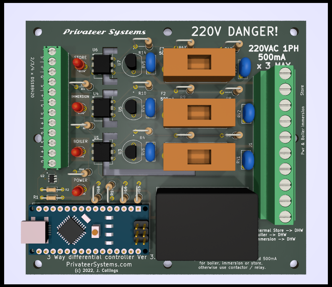
Inputs:
- Solar accumulation tank.
- Solid fuel boiler (such as wood gasification).
- Electric resistive heater (immersion heater).
If the domestic hot water temperature is below a preset limit, the controller will check to see if an input source temperature is hot enough to heat the domestic hot water. Inputs are prioritised in the list order, above.
Basic function
The basic function of the controller is to conserve the domestic hot water temperature (DHW) and stop it from dropping as the output from the solar system or boiler cools down. Solar or boiler heat is transferred through the tank’s heat exchangers, whilst DHW temperature is retained; there is heat gain, but not loss. In the case of solid fuel boilers, systems with circulator pumps tend to bleed heat back to the system until the pump stops. Older systems that used convection alone did not suffer from this if the tank was high enough.
If no other source of heat is available, the immersion heater is activated.
Once configured, the controller will operate without intervention.
The controller is fully digital and flexible. It uses Dallas/Maxim digital temperature sensors and can drive three thermo-actuated valves or relays, whose individual load current must not exceed 500mA. In this way is is possible to operate pumps and other devices.
Valves. We suggest Siemens STA23 actuator valves. These actuators give many years of life and operate with a wax capsule that, when heated, expands. This moves a valve – in much the same way as a radiator’s thermostatic valve operates.
Mode of operation
Mode of operation.

In essence, if the source output is cooler than the DHW + a margin (the Delta or ∆), the associated valve will be closed, otherwise, it will open.
There are four LEDs that indicate the state of the various channels: – STORE – DHW is being heated from hot water in the solar thermal store. – IMMERSION – DHW is heated by the electric immersion heater. – BOILER – DHW is being heated from the solid fuel boiler. – POWER – Device is powered up from external power.
The actual operation is more sophisticated:
Preferred DHW temperature. This can be set. In normal operation, the thermo actuator will close once the DHW reaches this temperature.
Maximum temperature that the immersion heater is allowed to heat to. Typically set less than the preferred DHW temperature to conserve electrical energy.
Delta ∆. This is the additional margin, after which a valve operates if a preset delta T (temperature difference) is exceeded between source and tank. This is needed because different heat exchangers have different efficiencies, and pipework between systems allows heat loss. Delta is configurable and is typically a few °C.
Hysteresis ⎎. A configurable hysteresis can be set. Typically set to 2°C, this stops the valve repeatedly opening and closing around the setpoint, because ‘on’ will always be x°C above ‘off’.
Minimum operating temperature. Solid fuel boilers need to reach a certain temperature to operate properly. This can be set so that the thermo actuator for that circuit will not operate unless this temperature is reached.
Clamping. Solid fuel boilers sometimes overshoot and it is beneficial to be able to absorb this excess heat. A clamping temperature can be set for the boiler, and when this is set, the valve will open.
Maximum DHW temperature. This can be set for both safety reasons and because some (plastic) pipework will not withstand high temperatures.
Absolute temperature limit is hard-set as 90°C.
Valve exercising. The controller will open and close the valve/s or operate the pump every 28 days of non-operation (typically during summer). This is to stop the valves or pumps from sticking. This cycle runs for 5 minutes, then it switches off.
The valve/s will be operated only when an appropriate combination of the above criteria is met so as to use the cheapest source of energy. In the worst case, the immersion heater is switched on.
Installation
All electrical work should be carried out by a qualified electrician. Install the controller in an appropriate plastic enclosure, in a suitable dry location inside the building, close to a power outlet, and close to the thermo actuators, solar store, boiler, and tank.
Connect:
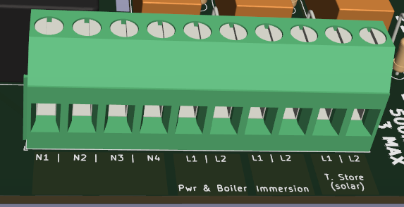
- Incoming 220VAC Power to ‘L1’ and ‘N1’
- The thermo actuator valve for the boiler/tank heat exchanger to ‘Pwr & boiler’ ‘L2’ and ‘N2’.
- A suitable immersion heater relay to ‘Immersion’ ‘L2’ and N3. ‘Immersion’ ‘L1’ will need power, either from mains (‘Pwr & boiler’ ‘L1’), or through a cheap rate tariff control circuit. The power you provide to ‘Immersion’ ‘L1’ will be switched on and off by the controller.
- If you have a thermal store, and want to use this to either heat or pre-heat your domestic hot water, use the ’T. Store’ connections to operate a relay to run a circulator pump. Again you will need to provide power to ’T. Store’ ‘L1’ and ’T. Store’ ‘L2’ will be switched on and off by the controller.
- Dallas sensors have three wires and operate at 5vDC. Typical colours: black is neutral, red is +5C, and yellow signal. Connect them so:
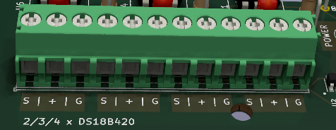
- Black to ‘G’ (ground)
- Red to ‘+’ (power)
- Yellow to ‘S’ (signal)
- Place one sensor on the boiler output in a thermowell or pipe clip with good thermal conductivity. Be careful not to crush the sensor. A small bed of high-temperature RTV silicon will improve the thermal conductivity between pipe and sensor considerably if you don’t use a thermowell; but in this case ensure that the sensor is insulated from the surrounding air.
- Place the other sensor in a thermowell in the top section of the DHW tank, at a level above the appropriate heat exchanging coil. Alternatively slip it under the insulating jacket touching the DHW tank wall, or attach it to the DHW outlet pipe next to the tank.
As with all solid fuel DHW installations, it is advisable to have a thermostatic mixing valve (such as ESBE) installed at the outlet of the DHW tank. This is particularly important with installations that supply DHW to the elderly or children, whose ability to recognise and react to temperature extremes may be diminished.
Configuration
Download and install a serial terminal application on a device such as an Android phone. ‘Serial USB Terminal’ by Kai Morich works well.
Disconnect the device from the mains and plug the phone into the controller’s external USB port with a suitable OTG cable.
Connect to the controller at 9600 baud, ASCII.
The controller will re-start, using power from the phone. During this, you may see similar text:
Differential Temp (c) James Collings, 2022
PrivateerSystems.com

V: 3.1

Init DS1820 T sens: 2 found
0=28FFF854C317452 - ROM Fake? 28-xx-xx-xx-xx-00-00-crc
1=28FFF532C41745D - ROM Fake? 28-xx-xx-xx-xx-00-00-crc
......... ok!
(The above indicates that the controller detected 2x non-genuine temperature sensors.)
Afterwards, a menu will appear:
Main
====
S      Settings
V      Verbose
R      Restart
================
'L'etter selects
Enter ‘S’, followed by ‘Send’ or [enter] (depending on your terminal emulator)
You will see the settings:
[Settings]
==========
Sensors found:
0=28FFF854C317452:20.06
1=28FFF532C41745D:20.00
==========
Assign sensor to address
eg T=1
T tank                    : 28FFF854C317452
U source                  : 28FFF532C41745D
H ts dhw                  : 28FFF854C317452
L thermal store           : 28FFF532C41745D
O immersion               : 28FFF854C317452
==========
K tanK desired temp       70.00 [60.00~90.00]
D source - tank Delta     5.00  [0.00~90.00]
W dhW-therm store delta   5.00  [0.00~90.00]
R min souRce temp         6.00  [0.00~90.00]
C source Clamp temp       82.00 [0.00~99.99]
X maX tank temp           90.00 [0.00~90.00]
N immersion               20.00 [0.00~90.00]
Y hYsteresis c            1.00  [0.00~3.00]
B Boiler enabled          1     [0~1]
I Immersion enabled       1     [0~1]
E TS enabled              0     [0~1]

'L'etter selects 'L=V'alue sets
===============================
M = Menu
Assign the appropriate sensor index to the tank and source. They will be listed and you can see the temperature of each to help you determine which is which. For example, enter ‘T=1’ [enter] to assign sensor 1 to the tank. After changing the sensor addresses you will need to restart the device. The equals sign is optional. The range is displayed to the right: [60.00~90.00].
Enter the desired tank/DHW temperature as: ‘K=71.5’ [enter] or whatever your choice is. The range is given to the right. For the tank, it lies between 60 to 90°C. This is to avoid legionella.
Set the Delta ∆. Typically set to 5°C This is the difference between the source and the tank in celsius after which the controller will activate the valve (assuming other conditions are met).
The minimum source temperature should be set high enough to avoid condensation in the boiler or flue. If you are using an alternate heat source, such as solar, set this to a low value, or 0.
The Clamping temperature is that at which the controller will attempt to smooth out any boiler heat spikes by opening the valve to absorb them into the DHW. A good value is just a couple of degrees over the nominal value of your boiler or other installation.
The maximum tank/DHW temperature should be above the desired tank temperature, but not so high as to cause danger to plastic pipes or people.
The hysteresis ⎎ should typically be set around 1 to 2°C. This stops short cycling of the valve when sensor temperatures are on the threshold of turning the valve on and off.
Entering B0 or B1 disables or enables the boiler channel.
Entering I0 or I1 disables or enables the immersion heater channel.
Entering E0 or E1 disables or enables the solar thermal store channel.
Setting up the Dallas sensors.
Each sensor has a unique address burned into it. You need to associate the address with either the tank or the boiler (source). Many of these sensors that are on the market are not original Dallas/Maxim ones and they may not work properly.
The controller attempts to determine if their ROM codes are valid Maxim ones at startup and you will see this if you watch with a terminal emulator connected.
When you update a value, the controller will store it in its EEPROM memory, and these values will remain between restarts and power on/off events.
Operation
You will see the valve/s open and close as appropriate.
Troubleshooting
Plug the USB serial device into the controller. You will see the active status. You can increase the verbosity of the messages by pressing ‘V’’ [enter] from the main menu.
If the valve is not operating, ensure that it is free to move, getting power & correctly installed. Failing that, follow the manufacturer’s instructions.
If the sensors are reading lower than direct measurements indicate they should, improve conductivity to the pipe (eg. bed them in high temperature RTV silicon) and insulate them.
Technical
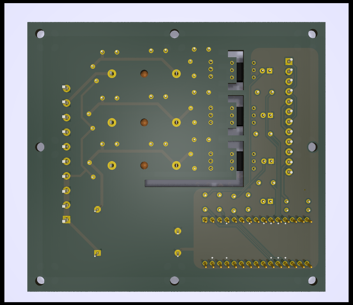
The controller uses a pre-programmed module with an Atmel 328 processor, soldered to a small motherboard. The motherboard has a quality Meanwell/Recom/Vigortronix power supply, fuses, varistors for surge suppression & flyback protection, optoisolated triac drivers, and small power triacs rated up to 1 amp. Power consumption is very low, typically in the order of a few mW. The power triacs need at least 6mA of current to pass through them to operate, and the STA23 valve draws enough, as does a typical relay / contactor coil. The motherboard has protection from overvoltage caused by electrostatic discharge (ESD) and electrical fast transients (EFT).
The physical components are minimal because of the microcontroller-based nature of the device; everything that can be done in software is done in software. This keeps it inexpensive and robust, and it allows upgrades with software only.
Siemens STA23 thermo actuator: (230 v, single phase, 50hz): during steady-state normal operation (when the unit is powered) uses 21mA. During powerup, which is momentary and transient, it draws 250mA.
Maxim DS18B20 1-Wire Digital Thermometer: measures temperatures from -55°C to +125°C and communicates over a 1-Wire bus with only one data line (and ground + power) for communication with a central microprocessor. Each DS18B20 has a unique 64-bit serial code, which allows multiple DS18B20s to function on the same 1-Wire bus. One microprocessor may control many DS18B20s distributed over a large area. Applications that can benefit from this feature include HVAC environmental controls, temperature monitoring systems inside buildings, equipment, or machinery, and process monitoring and control systems.
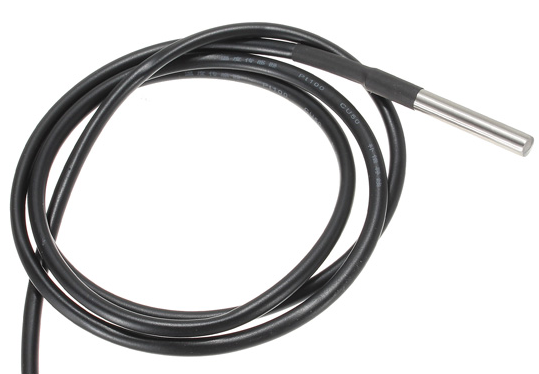
Reverse of pcb:
Why no app?
This device is expected to have a long life of many years – certainly beyond several iterations of phone operating systems, or even the systems themselves. It is not connected to the internet, and once set up should provide years of continuous operation without any intervention. It therefore makes no sense to provide such an interface; in fact it would potentially be detrimental to the reliability of the device.
Disclaimer:
Errors and omissions excepted. No reliance can be made upon the accuracy of the information contained herein, and no liability arising from the information and/or the use of the device is accepted. This device is a prototype only and not for sale.
